History of ARM
- Stands for Advanced RISC Machines
- RISC = Reduced Instruction Set Computer
- Originally developed at Acorn Computers Limited of Cambridge, England, between 1983 and 1985
- Licensed to many semiconductor manufacturers around the world
RISC
- It is a design aimed at delivering simple but powerful instructions that execute within a single cycle at high clock speed
- Concentrates on reducing the complexity of instructions performed by hardware because it is easier to provide greater flexibility in software than in the hardware.
- RISC design places greater demands on the compiler.
- In contrast, the CISC instruction set is more complicated because it relies more on the hardware for the functionality
- Each RISC instruction is a fixed length for pipelining purpose
- Pipelines: The processing of instructions is broken down into smaller units that can be executed in parallel
- Registers: RISC machines have a large general purpose register set. These registers can either contain data or an address
Load Store Architecture:
- The processor operates on data held in registers.
- Separate load and store instructions transfer data between the register bank and external memory
- Memory accesses are costly, CISC instructions act directly on memory which is very inefficient
- This design rule allows RISC to be simpler and thus the core can operate on higher clock frequencies.
CISC vs RISC
| CISC | RISC |
|---|---|
| Emphasis on hardware | Emphasis on software |
| Includes Multi-clock instructions, complex instructions | Single clock cycle, reduced instruction only |
| Memory to memory: LOAD and STORE are incorporated within the instruction set | Register to register: LOAD and STORE are independent instructions |
| Small code size, high cycles per second | Low cycles per second but large code sizes |
| Transistors are used to store complex instructions | Spends more transistors on memory registers |
ARM Design Philosophy
- Reduced power consumption
- High code density
- Price sensitive, use low cost memory devices
- Reduce the area of the die
- hardware debug technology
Instruction set for embedded systems
- Variable cycle execution for certain instructions
- Inline barrel shifter leading to more complex instructions
- Thumb 16 bit instruction set
- Conditional execution
- Enhanced instructions
ARM Core Data Flow model
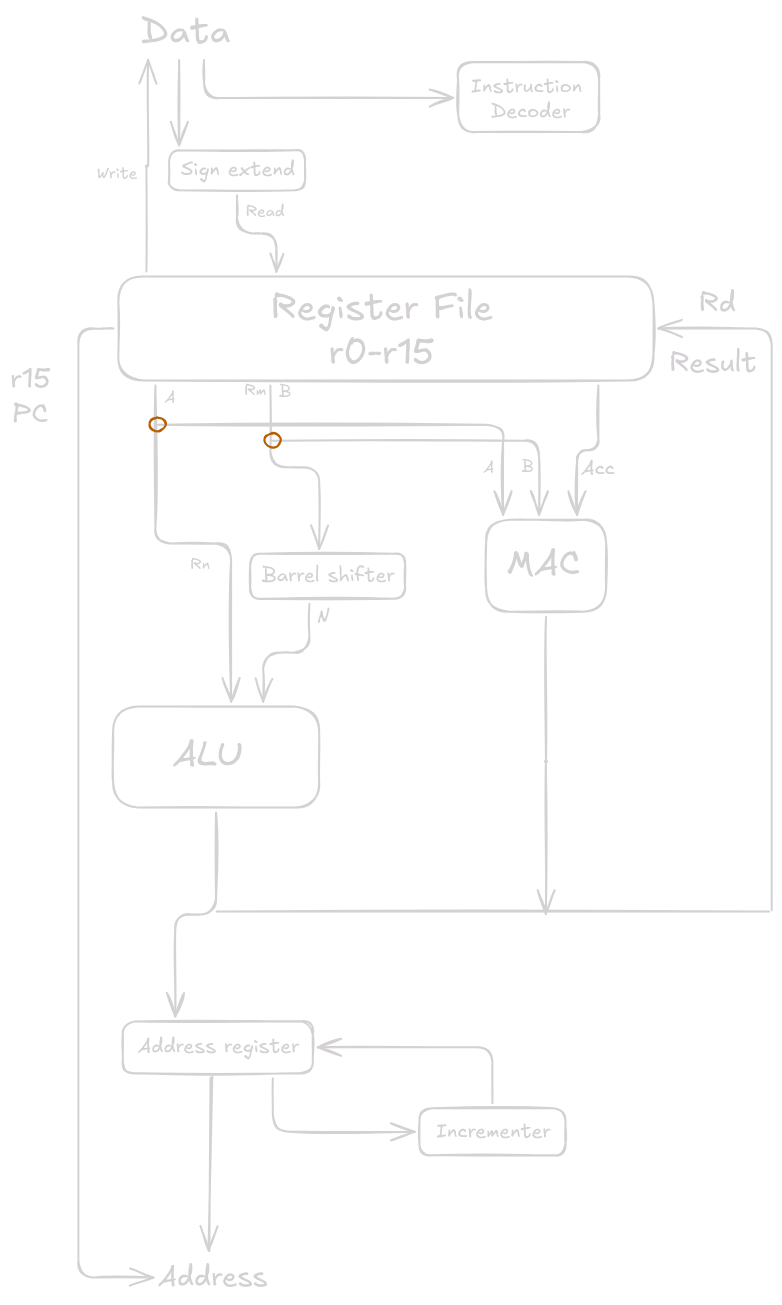
- The arrows represent the flow of data
- The lines represent the buses
- The boxes represent either an operation unit or a storage area
- This is a Von Neumann implementation of the ARM processor.
- The instruction decoder translates instructions before they are executed. Each instruction executed belongs to a particular instruction set
Working of ARM
- 2 Source registers: Rn and Rm
- 1 Single destination register: Rd
- Source operands are read from the register file using the internal buses A and B respectively
- The ALU (Arithmetic Logic Unit) and the MAC (Multiply-accumulate unit) takes the register values Rn and Rm from the A and B buses and computes a result.
- One important ARM feature is that register Rm alternatively can be pre-processed in the barrel shifter before it enters the ALU
- Together the barrel shifter and the ALU can calculate a wide range of expressions and addresses.
Registers in ARM
- General purpose registers hold either data or address
- All the registers are 32 bits in size
- Identified with the letter prefix “r”
- There are upto 18 active registers, 16 data registers (r0 through r15) and 2 process status registers cpsr and spsr (current and saved program status registers)
- Special function registers are r13, r14 and r15
- r13 is traditionally used as the stack pointer sp and is used as a pointer to active stack
- r14 is called the link register lr and used to store the return address from a subroutine
- r15 is called the program counter pc is used to track the address of the instruction it is about to execute
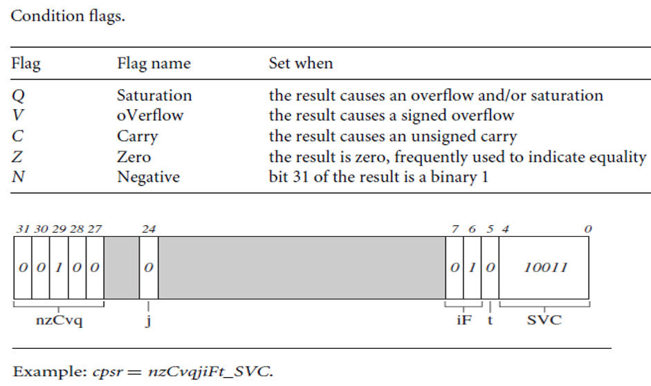
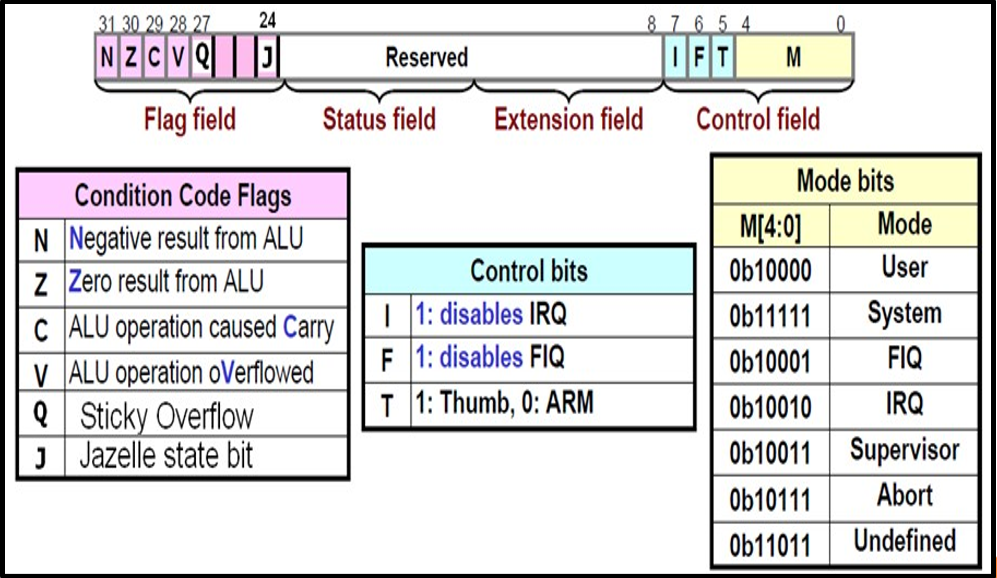
CPSR (Current Program Status Register)
- Register is used to monitor and control internal operations
- Dedicated 32 bit register in the register file
- Divided into 4 fields, each 8 bits wide
- flags
- status (future use)
- extension (future use)
- control
- Control field contains the
- Processor mode
- State
- Interrupt mask bits
Processor modes
- The processor mode determines which registers are active
- Each processor mode is either privileged or non privileged
- Privileged mode allows full read-write access to the cpsr
- Non-privileged mode only allows read access.
- There are 7 processor modes in total:
- Six Privileged modes (Abort, Fast Interrupt Request, Interrupt Request, System, Supervisor and Undefined)
- One Non-Privileged mode: user
Banked Registers
- 37 registers in the register file
- 20 are hidden and are called banked registers
- These registers are identified only when the processor is in that particular mode
- Every processor mode except “user” can change the mode by writing directly to the mode bits of cpsr
States
- The state of the core determines which instruction set is being executed. There are 3 instruction sets:
- ARM
- Thumb
- Jazelle
- The Jazelle J and Thumb T bits in the cpsr reflect the state of the processor.
- When both J and the T bits are 0, the processor is in the ARM state and executes ARM instructions. When the T bit is 1, it executes Thumb instructions.
- Jazelle instruction set is a hybrid mix of hardware and software designed to speed up the execution of Java byte codes.
- To execute Java bytecodes, Jazelle instruction set and a specially modified version of the Java virtual machine (JVM) is needed.
Interrupt Mask
- These are used to stop specific interrupt requests from interrupting the processor
- There are 2 interrupt request levels available on the ARM processor core
- IRQ (Interrupt request)
- FIQ (Fast interrupt request)
- The CPSR has 2 interrupt mask bits, 7 and 6 (i and f) which control the masking of irq and fiq respectively.
- The i bit masks IRQ when set to 1 and the f bit masks FIQ when set to 1
Condition flags